

CCD2 Installation
CCD2 Installation
Section titled “CCD2 Installation”Mounting
Section titled “Mounting”- Display:
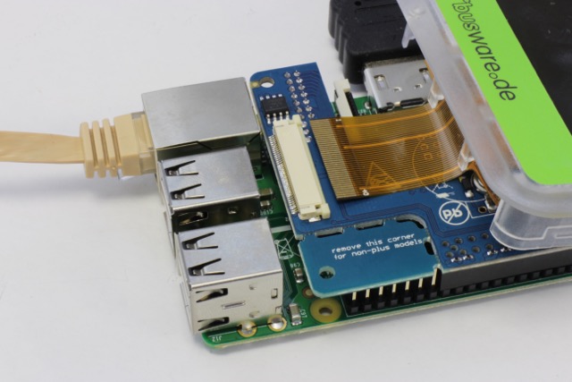
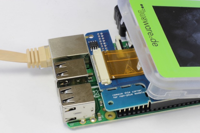
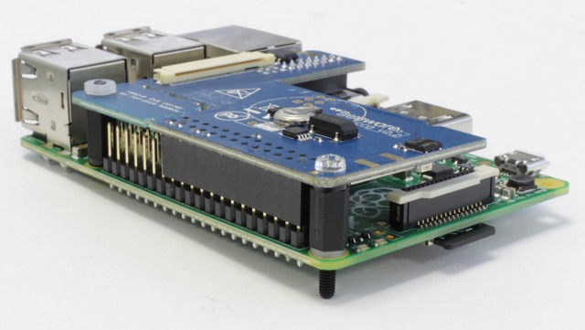
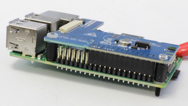
- stacking PCBs.
preparing Raspberry system files
Section titled “preparing Raspberry system files”Use an up-to-date image i.e. Raspbian - download
- remove any reference to ttyAMA0 inside /boot/cmdline.txt and /etc/inittab
- add to /boot/config.txt
dtparam=spi=on dtparam=i2c=on dtoverlay=ads7846:cs=1,speed=2Mhz,penirq=25,penirq_pull=0,xmin=200,ymin=200,xmax=3900,ymax=3900,pmin=0,pmax=255,xohms=60,swapxy=0
- add to /etc/modules
spi-bcm2708 i2c-bcm2708 i2c_dev fbtft_device ads7846
- create file /etc/modprobe.d/fbtft.conf
options fbtft_device custom name=fb_ili9341 dma=1 buswidth=8 speed=48000000 gpios=reset:23,dc:24,led:22 rotate=90 bgr=1 cs=0
- reboot
Display
Section titled “Display”to test the display do:
fbcp & omxplayer movie.avi
Further instructions here
Touchscreen
Section titled “Touchscreen”to test the touch screen do:
evtest /dev/input/event0
Further instructions here
RTC clock
Section titled “RTC clock”add to /etc/rc.local
echo ds1307 0x68 > /sys/class/i2c-adapter/i2c-1/new_device sleep 1 hwclock -s
remove fake-RTC:
apt-get remove fake-hwclock rm /etc/cron.hourly/fake-hwclock update-rc.d -f fake-hwclock remove rm /etc/init.d/fake-hwclock update-rc.d hwclock.sh enable
The IR-receiver is connected to GPIO4
start radio chip by:
if test ! -d /sys/class/gpio/gpio17; then echo 17 > /sys/class/gpio/export; fi echo out > /sys/class/gpio/gpio17/direction echo 1 > /sys/class/gpio/gpio17/value
add to fhem.cfg:
define CSM CUL /dev/ttyAMA0@38400 0000
Firmware update
Section titled “Firmware update”You must stop FHEM before doing:
make -C /path-to-local-GIT-clone/culfw/Devices/CCD2 program